
RC Baja
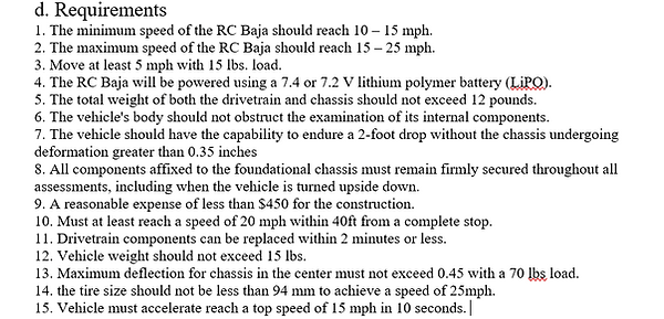
Drivetrain & Chassis
Engineering Report
Fall Presentation
Winter Presentation
Spring Presentation

Introduction
The purpose of this project involves the development of a functional product aimed at meeting specific objectives and requirements, offering a tangible solution or innovation to address a particular need or issue. Annually, the MET program at CWU organizes the RC Baja race competition just before the conclusion of the Spring quarter, providing senior students with the opportunity to compete amongst themselves and showcase their distinct designs. Moreover, the primary goal of this endeavor is to utilize engineering techniques to conceive and construct an RC Baja car with a chassis and drivetrain capable of effectively participating in the ASME RC Baja competition. Additionally, the project's success hinged on the collaborative efforts of the team, particularly in handling the suspension and steering system.
Design Sketches

Alternate Design

Main Design
Results
The project's outcomes deviated from the student's expectations. While the predicted value for the speed test was 25 mph, the achieved average across five trials was only 6.4 mph. However, the results of the deflection test proved significant for meeting the project requirement, which stipulated that the chassis must not deflect at the center by more than 0.45 inches.
Table 1:Max Deflection results with different loads.
Passed The requirement

The maximum amount of deflection observed under a 100-pound force was 0.05 inches, consistently maintained for forces ranging from 100 to 125 pound- force (lbf).
Table 2: Figure 5: Average top speed
Didn't Passed The requirement
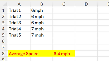
In five trials covering a distance of 40 feet, the RC car achieved an average maximum speed of 6.4 mph.
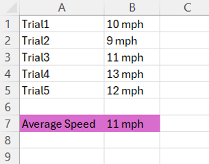
In the second speed test the RC car the achieved an average maximum speed of 11 mph which is better than the first test result.
Table 3 : Acceleration Data
Didn't pass the requirement

In third test test for the RC car was an acceleration test. The calculated value was 3.67 ft/^s. However, after conducting the test it appears that the average acceleration is to be 2.68 ft/^s
Analysis
The provided introduction sets the stage for a year-long, in-depth exploration of website analysis. Over the course of the year, the focus will be on gathering and presenting all the necessary analytical data required for designing the parameters of the RC Baja. This analytical journey will encompass various aspects of website analysis, including performance metrics, user behavior, and design elements. By consistently monitoring and evaluating these key factors, the goal is to provide a solid foundation for the design and development of the RC Baja, ensuring it meets the intended specifications and offers an optimal user experience. This year-long commitment to website analysis is expected to be instrumental in the successful realization of the RC Baja project.

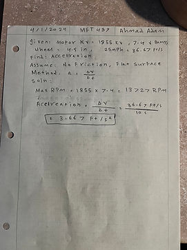
The purpose of this Analysis is to achieve a peak velocity of 11.176 meters per second for a vehicle weighing 9.53 kilograms and fitted with 70mm diameter tires, the need arises for a motor with specific performance characteristics. To accomplish this, the motor must be capable of generating approximately 3050 revolutions per minute (RPM) and delivering around 8.73 Newton-meters (Nm) of torque. These motor specifications are crucial for providing the necessary power and rotational force to propel the vehicle to its desired speed. With these performance parameters, the vehicle can efficiently overcome its mass and the resistance from the road, ultimately reaching the desired peak velocity of 11.176 m/s, ensuring a smooth and reliable transportation experience.
Figure 1:Maximum RPM and Torque Calculations

The analysis conducted provides a clear understanding of the power requirements essential to achieve a maximum speed of 25 miles per hour within a 15-second timeframe. The methodology employed in this analysis takes into account acceleration and power equations to draw its conclusions. According to the findings, a minimum of 67.45 Watts of power is imperative to meet the necessary acceleration to reach the desired speed. This insight is of utmost significance for any project or endeavor that involves the acceleration of a given mass to attain a specific velocity within a specified time frame, as it sets a clear benchmark for the power output requirements to achieve the desired outcome.
Figure 2: Power Needed for Acceleration Test

The primary objective of this analysis is to ascertain the maximum deflection at the center of the chassis under the influence of a 70-pound load, which is applied to the midpoint of the vehicle frame. The chassis, designed with a thickness of 0.175 inches, a height of 14 inches, and a width of 11 inches, employs aluminum as the chosen material. Through rigorous structural analysis and calculations, it is essential to determine whether the selected aluminum chassis can withstand the applied load without experiencing excessive deflection, ensuring the structural integrity and safety of the vehicle. This examination represents a critical step in the engineering process, guaranteeing that the chassis meets the necessary strength and rigidity requirements for its intended application.
Figure 3: Maximum Deflection on the center of the chassis

This analysis was performed to determine the minimum required friction coefficient of the tires needed for the car to climb up a 45-degree incline, requirement 5 from section 1d. It was determined that the minimum coefficient need was 5.094, based on average car tire friction coefficients, a tire with a friction coefficient of 0.6 will be used for the RC car.
Figure 4: Needed Friction Coffecient

In this analysis, the maximum speed of the car was determined. The results show that the car will achieve a speed of 18 mph within a distance of 40 feet.
Figure 5: Maximum Speed
The purpose of analysis was to find the acceleration capability of the motor and vehicle. In the analysis, the calculated value for the acceleration was 3.67 ft/s^2,
Figure 5: Acceleration
Construction
The majority of components required for constructing the RC car will be produced through 3D printing, complemented by machining certain parts using the available facilities within the school. The choice to proceed with in-house manufacturing was influenced by the accessibility of essential equipment on campus, including 3D printers, milling machines, lathes, and calipers. The utilization of these tools guarantees the comprehensive assembly of the vehicle.

Drawing Tree
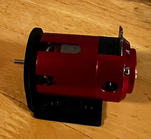
Figure 01 ( Motor Mount)
The component was produced utilizing a 3D printer within the school premises. The decision to opt for this method was driven by its cost-effectiveness and the convenience of having the necessary equipment readily available on campus. Utilizing the school's 3D printer not only proved to be a economical choice but also ensured easy access to the technology, streamlining the manufacturing process.
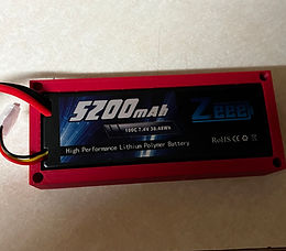
Figure 03 ( Battery Mount)
The part was manufactured utilizing the school 3D printer to create a battery mount for the Battery. This holder keeps the battery in place securely, so it won't move during the testing phase.
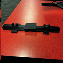
Figure 02 ( Rear Axle Housing)
The decision to 3D print the housing was made based on ease of manufacturing. Machining the part would be too complex and it would increase the risk of error and imperfection of the part. Also, if an error was made the cost would be significantly more than 3D printing the part.

Figure 04 ( Rear Axle)
The rear axle was manufactured using the lathe machine. Utilizing a lathe, to refine a metal piece to form the rear axle The lathe rotates the metal while the student meticulously shapes it with cutting tools. It's akin to sculpting the axle from a solid metal block, ensuring it attains a smooth and precise finish suitable for fitting into the vehicle's framework.

Figure 05: Picture of 3D printed template ( Right). Picture on the Left shows the Aluminum chassis

Figure06: Chassis set on the vertical bandsaw with marks to show the final dimension to cut.

Figure07: Finished Chassis

Figure 08: Video of utilizing the vertical bandsaw to make the chassis with appropriate dimensions.

Figure 09: video of utilizing the Lathe to make threads to the rear Axle

Figure10: Shows bearings set on the housing to hold the axle in place.

Figure11: Rear Axle fits the housing and sits perfectly
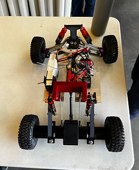
Figure12: Top view of finished car

Figure 13: Front view of the RC car with LED lights
Testing
Testing the RC Baja involves a comprehensive assessment of its durability, performance, and safety in off-road conditions. Emphasis is placed on the vehicle's ability to navigate rugged terrains, evaluating aspects such as speed, handling, and overall reliability. Predictions of performance cover top speed, acceleration, stability, and the robustness of key components like suspension, tires, and chassis. Safety features, including remote control range and emergency shut-off mechanisms, are scrutinized to ensure safe operation. These tests are vital to confirming the RC Baja's fitness for its intended purpose, whether recreational use or competitive off-road racing. A simulated race, resembling the ASME competition, is conducted to gauge the car's performance and troubleshoot any issues that arise, ensuring a thorough evaluation of its capabilities.
The initial test for the RC Baja involved checking how much the center of the car chassis could bend under a weight of 100-pound force. The material that was picked Aluminum 6061 T6 for the chassis, which has a modulus of elasticity of 68.9 GPA. During the fall quarter, the student did some calculations to find out the maximum amount the chassis could bend, and it turned out to be 0.05 inches, meeting requirement. This test was done to satisfy the requirement of the chassis not deflecting more than 0.06 inches.

Figure01: Load applied on the center of the chassis
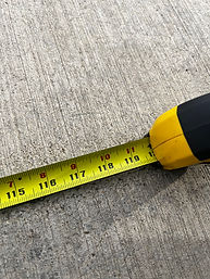
Figure 02: The measurement of 40 feet was conducted in increments of 10 feet.
.jpg)
Figure 03: The car was prepared to start the speed test by aligning the front tire with the starting marker.
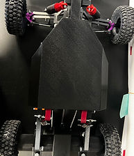
Figure 04: 3D printed cover designed to protect the RC components.
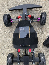

Figure 05: Complete car with cover and pumper.
Figure 05: The Speedometer app was used to record the data for the speed test.
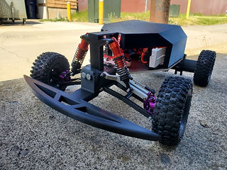
Figure 06: Front View of the complete Car
Figure 06: Video footage showcasing Sheila, the RC car, in motion.
Budget/Schedule
The design schedule for the Fall quarter of the Baja car project primarily focused on sketching and analysis, ensuring a steady progression of the project on a weekly basis. Several methods, including Green Sheets, Gantt Charts, and Progress Status Reports (PSRs), were employed to document and track the project's overall goals. A weekly drawing submission deadline was established to maintain momentum. The objective was to complete specific tasks listed in Appendix E by the end of the Fall quarter to facilitate the submission of a project proposal.
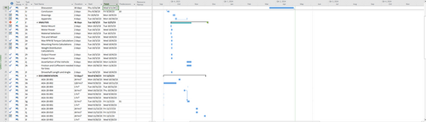
The construction schedule for the Fall quarter is outlined in Appendix E. The goal is to bring the project up to speed during the Winter quarter to enable the planned commencement of car construction, with the procurement of necessary parts and hardware scheduled for the beginning of the quarter. Furthermore, there are inherent risks associated with the project timeline, including constraints on equipment access, unpredictable weather conditions, and the potential unavailability of team members. The schedule below shows the process plan of manufacturing the RC Baja. During winter quarter, the student began manufacturing the car components to be ready to present a working device by the end of the quarter. Spring quarter, will manly focus on testing the device and evaluating the performance through variety of tests. The first test of the RC car involved subjecting it to a deflection test towards the center of the chassis while bearing a load of 100 lbs. This evaluation aimed to assess the structural integrity and durability of the vehicle under stress. Following this initial examination, the second testing phase entailed conducting a top speed test, covering a distance of 40 ft in the outside area of the Fluke lab. This test was designed to evaluate the RC car's performance capabilities in terms of speed and acceleration within a specified distance. Overall, The testing process for the RC car began with the student conducting a deflection test as outlined in Task 6a, detailed in Appendix E. Originally, the plan entailed initiating the speed test as the primary evaluation; however, encountered issues during preliminary testing led to the burnout of both the motor and ESC. Consequently, a minor adjustment was made to the testing sequence to address these setbacks. Despite these unforeseen delays, the tests were carried out in a timely manner, and were completed before the RC Baja competition, which was the hard deadline for functionality of the RC car.
Gantt Chart (Spring Quarter Updated )


Budget
The students have compiled a table in Appendix C that includes a comprehensive list of parts for their project, comprising both items to be purchased and those to be manufactured. The initial entry in this list is the Track Star ROAR Approved (13.5T) 1/10th Stock Class Brushless ESC and Motor Combo, which will be procured from hobbyking.com for an estimated price of $82.99, designated as part number 55-004. As the quarter advances, team members will develop a more precise grasp of the parts necessary for their manufacturing endeavors in the upcoming Winter Quarter. Furthermore, Appendix D displays both the labor costs and the anticipated overall expenses associated with the project. After purchasing the remaining components of the chassis such as, the locking nuts, bearings, wheel hex the total increased to 405.93$ which raised the total budget of the project to 6530.93$
During spring quarter, the team has to purchased a new ESC and motor because both components have burn out resulting in buying new components to carry on with the remaining tests. Replacing the ESC (Electronic Speed Controller) and motor due to burnout during the spring quarter can be a setback, but it's also an opportunity to learn and improve. The team went over the budget that was assigned at the beginning of fall quarter. The initial budget was estimated to be around $500 but after purchasing the new components it want up by 26% over the budget.
Table C. Parts List (spring quarter Updated)

Table D. Parts List (spring quarter Updated)
